Home › Forums › Electronics Restoration › What is this from 1924 Aladdin Big Four?
- This topic has 8 replies, 5 voices, and was last updated 7 years, 4 months ago by
 Ed Kraushar.
-
AuthorPosts
-
March 2, 2019 at 7:57 am #11157
HolderAccount
Forum ParticipantNeed to know what it is and where to get them. Or perhaps some substitute part.
Including images of part and where it came from.Thanks
-
This topic was modified 7 years, 4 months ago by
HolderAccount.
March 2, 2019 at 11:02 am #11162 garykusterForum Participant
I’m pretty new to this, but it looks like a fuse. Have you checked it with a meter?
March 2, 2019 at 11:17 am #11163 Rick DForum Participant
Hi Aladdin
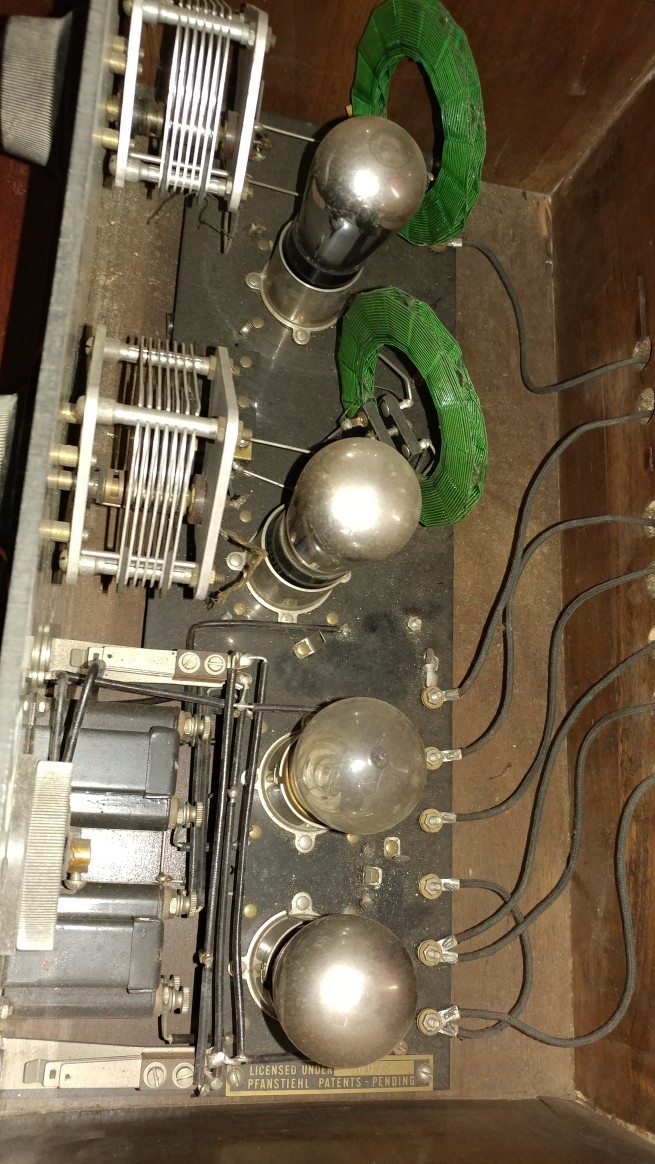
That I am sure is a Grid Leak Resistor,on my battery 1920,s sets, they are around 2 Meg,put your meter tips
on both ends and see what you get,looks like it goes beside your detector tube,most of mine go there,it is the
only tube that takes 45 volts all the other tubes take 90 volts.If you look at your set two tubes down from the
top of the photo with the tubes you will see a small clip with a hole in it ,that hole is where the end of the resistor
fits in to hold it in place,if you look across from that clip you will see a hole and a darker spot of black ,thats where
the other end of the clip that also holds the grid leak resistor used to be.You can if you want just put in a regular
resistor of the same value,Gary at Play Things Of The Past has many of these Grid Leak Resistors ,just google
play things of the past for his web site,Garys prices I find are the best and it gets here fast,if you have any problems
let me know ,I have a few spares ,all the best RickMarch 2, 2019 at 11:50 am #11164Forum ParticipantRick D
Thank you, thank you, thank you!
Just read about grid leak detector on wiki. I will meter the 3 when I get a chance. This will be my first restoration project. If successful my 1936 Rogers Tombstone, 1946 Philco and 1960- ish Hotel radio will be next.-
This reply was modified 7 years, 4 months ago by
Attachments:
March 4, 2019 at 6:52 am #11180Forum Participant1 metered 640 ohm
1 was 2.6 mega
1 was 3.6 mega
Anybody have am Aladdin Big Four schematic?
What should the 3 grid leak values be?March 4, 2019 at 12:35 pm #11181 Ed KrausharCVRS Member
What is the size of those “grid leaks”. The one in your picture looks more like an amperite, a ballast in the filament circuit.
A grid leak is about 1/4 ” diameter by 1 3/4″ long.
An amperite is about 7/16″ by 1 7/8 inches and has a black fibre casing.
Ed.March 6, 2019 at 7:11 am #11186Forum ParticipantOk, it’s an amperite. The is 3 of them.
Looking amperite up on Google.March 9, 2019 at 11:37 am #11190 Gerry O’HaraCVRS Member
The grid leak value is usually not critical. Try anything between 1Mohm and 4Mohm. If the old grid leak resistor has gone open circuit or drifted way-high in value, just insert the new resistor into the socket and hold in place with the old grid leak cartridge.
March 9, 2019 at 1:03 pm #11192Ed KrausharCVRS MemberThese are ballasts, not grid leaks. They are in series in the filament circuit of the tubes and are usually of low resistance. Their purpose is to regulate the voltage going to the tube filaments. If a megohm resistor is used to replace them the tubes will not get any voltage. I have jumped them with low value resistors when open.
Radio Museum shows them in a partial schematic of the Aladdin Big Four.
Ed. -
This topic was modified 7 years, 4 months ago by
-
AuthorPosts


- You must be logged in to reply to this topic.