Home › Forums › Show & Tell › Phonola 40B41P restoration
Tagged: home brew power supply
- This topic has 8 replies, 6 voices, and was last updated 5 years, 4 months ago by
 Kurt Draper.
-
AuthorPosts
-
July 4, 2020 at 1:21 pm #14998
 Kurt DraperCVRS Member
Phonola 40B41P
The Phonola 40B41P is a four tube battery table radio. It was manufactured in 1940 by Dominion Electrohome Industries LTD in Kitchener Ontario Canada. It was an internet purchase from a vendor in Barrhead Alberta Canada. The seller bought it at a garage sale. An older couple was downsizing. He didn’t know any other history on it. The purchase price was $120.00 shipped to my door.
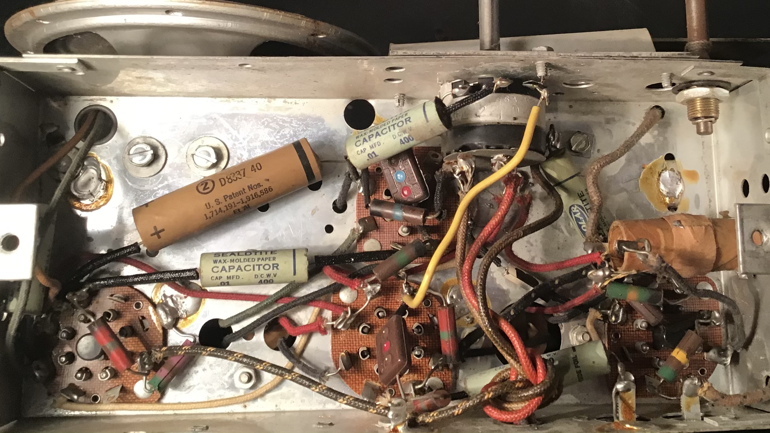
The tube complement consists of a 1A7 converter/local oscillator, 1N5 intermediate frequency amplifier, 1H5 detector/first audio amplifier, and a 1C5 power output. It requires a 1.5 volt filament battery and a 90 volt B battery. It receives the broadcast band only. All but the power output tube are CGE (Canadian General Electric) branded and probably original. The 1C5 is Westinghouse branded. It uses a superheterodyne circuit. To start repairs, I replaced all five paper capacitors and the one electrolytic capacitor. The electrolytic capacitor was housed in a cardboard tube and was restuffed. The paper capacitors are Solar branded and are molded wax with a paper label affixed. In an attempt to reproduce these, I stuffed the new capacitors in small cardboard tubes. These tubes are NGK spark plug packaging I obtain from work. I attempted to remove the labels from the original capacitors. I heated them with a heat gun. I attempted to remove the labels with a small screwdriver. This attempt failed. I’ll have to figure out a way to scan them into a computer and print them on labels. At this point I connected my home brew power supply and turned it on. It came alive and worked. It received stations across the dial with good volume.
The cabinet was in a condition that it was hard to make a decision on how to fix it. The center dark brown section had a pattern sprayed on that I wasn’t sure how to reproduce. I decided to attempt to save the finish on the front and sides. The front and sides were sprayed with Blender Flow Out, then clear, then Blender Flow Out And more clear. This worked pretty well except there was a couple places the finish crazed. I sanded the crazed areas with wet dry 600 grit sandpaper wetted with mineral spirits. Then I sanded the whole cabinet with 800 grit wetted with mineral spirits. After that dried, I gave it another coat of Blender Flow Out then clear. It turned out pretty decent. The top had a large chunk of veneer missing. The remaining part was scraped off with a large scraper. A new piece of veneer was glued on with Weldwood Contact Cement. It was then sanded and a coat of Constantine’s oak grain filler applied. The top was sprayed with black lacquer followed by some clear satin lacquer. The original grille cloth was in good condition and reused. The dial lens was cleaned with 3M plastic polish. This is an essay I wrote. I show some radios from my collection at three local antique machinery shows in my area (Valparaiso Nebraska). For as simple as it is, it works very well and has nice tone. If anyone from the Barrhead / Edmonton region reads this I would be interested in hearing some history from this region. This is my first post. When I or more likely my wife figures out how to add pictures, I will.July 4, 2020 at 5:11 pm #14999HolderAccount
Forum ParticipantWould love to see some pictures. It sounds like you did a good job.
July 7, 2020 at 12:19 pm #15025 Gerry O’HaraKeymaster
Those little Phonola sets are great – I restored one a few years back and I really love it. Some photos attached. It was in a bit of a state when I obtained it (I think it had been left outside on a doorstep for a few years!). I installed a small power supply inside the cabinet. Its a Model 1B4L-1P.
Gerry
-
This reply was modified 6 years ago by
 Gerry O'Hara.
July 7, 2020 at 6:31 pm #15032Gary Albach
KeymasterLooking forward to seeing the pictures. As for fabricating replacement Solar capacitors, I’ve had mixed results soaking the labels off in warm water. They’re pretty flimsy but you can scan and fix up the blemishes in a photo editing program before printing them.
Gary in VictoriaJanuary 24, 2021 at 5:46 pm #16094Kurt DraperCVRS MemberHere are some pictures of the Phonola.
January 24, 2021 at 6:00 pm #16099Kurt DraperCVRS MemberHere are some different pictures of the Phonola.
January 24, 2021 at 6:19 pm #16103KeymasterVery nice, Kurt. How did you scan the Solar capacitor labels before printing new ones?
Gary in VictoriaJanuary 26, 2021 at 8:38 am #16119 Les DicksonCVRS Member
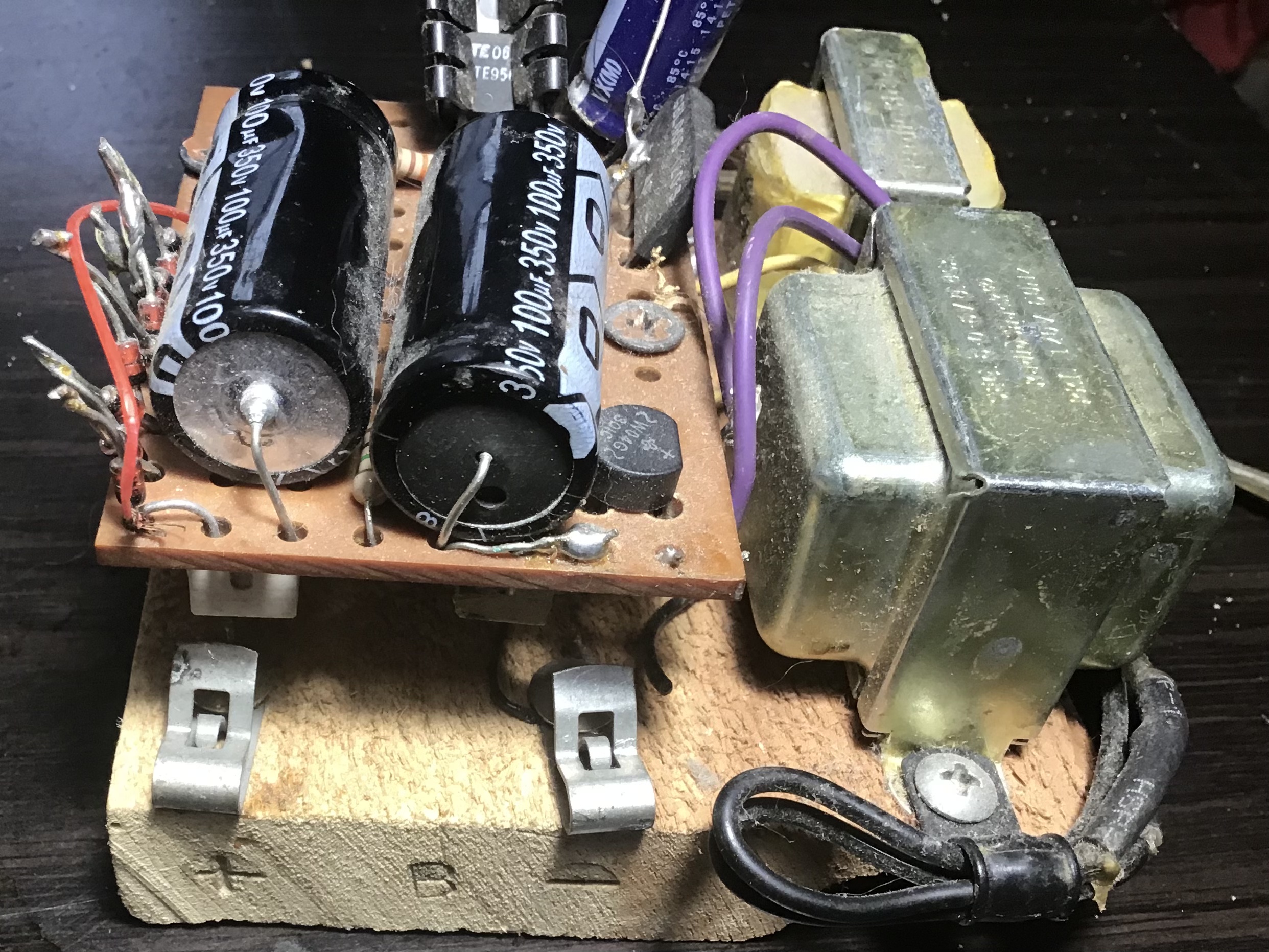
Wonderful job, Kurt! Would you be willing to share the details and/or schematic of your home brew power supply?
March 14, 2021 at 5:19 pm #16435Kurt DraperCVRS MemberTo power these, I started out with the power supply Antique Electronics Supply used to sell. Mine works great but I had to switch it between the two battery powered radios I had at the time (of course I have more now) and change the A voltage. I then decided to build one for each radio. The transformers I purchased from Radio Shack. Another supplier would need to procured since they are no longer in business. I also purchased the bridge rectifiers, resistors, regulator and low voltage capacitors from them. I started with two 120/12.6 volt transformers with the secondaries wired together. The A supply is tapped off the 12.6 volt section. The A supply is a direct copy of the Antique Electronics Supply design. The only change I would make is once I determined the correct resistances needed to produce the correct A voltage, I would install fixed resistances instead of the potentiometer. The B supply is similar. The negative side if the bridge is B-. The positive side goes to a 100mfd 350 volt capacitor, a 1k 5 watt resistor, another 100mfd capacitor, a second 1k 5 watt resistor then a string of 12 zener diodes to B-. Then pick the junction between zeners that is the closest to the voltage required. It works well. The larger the heat sink on the LM 317 voltage regulator the better. It holds with the smaller black one I used but it gets pretty warm with 4 or 5 1.4 volt tubes. I show radios at a few local antique machinery shows. I decided for 2019, I would actually run them off of batteries. For the 1.4 volt 90 volt radios like the Phonola I used two alkaline D cells in parallel for the 1.4 volt A supply and 10 nine volt carbon zinc batteries in series for the B+. My Coronado 650 is a 2 volt 90 volt so I used the Enersys lead acid sealed glass mat battery for the A battery. I used two groups of 5 nine volt batteries for the B+. The Airline 62-211 I showed used a Enersys for the A supply. I used 15 (3 groups of 5) nine volts for the B+. It needed taps for 67.5, 90 and 135 volts. I used combinations do triple A and nine volts for the C supply. It all worked out well and they lasted a lot longer than I thought they would.
-
This reply was modified 6 years ago by
-
AuthorPosts


- You must be logged in to reply to this topic.