Home › Forums › Electronics Restoration › Bias Cells
- This topic has 6 replies, 3 voices, and was last updated 9 months, 3 weeks ago by
 Brad Winder.
-
AuthorPosts
-
July 29, 2008 at 7:45 am #1102
 Gerry O’HaraKeymaster
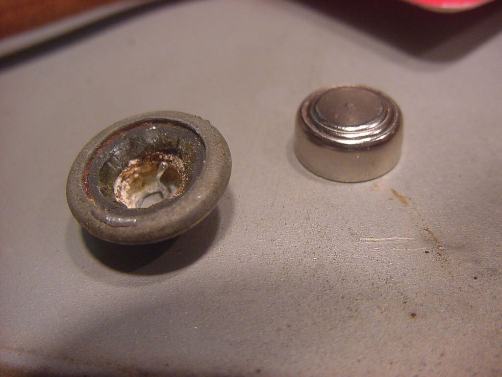
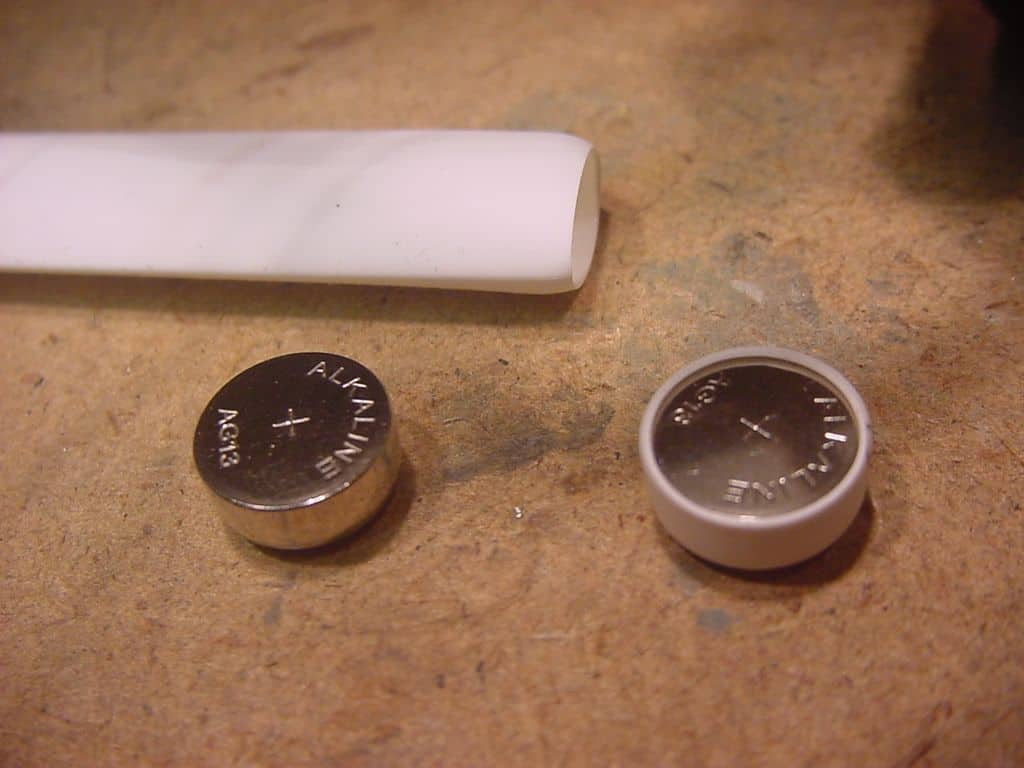
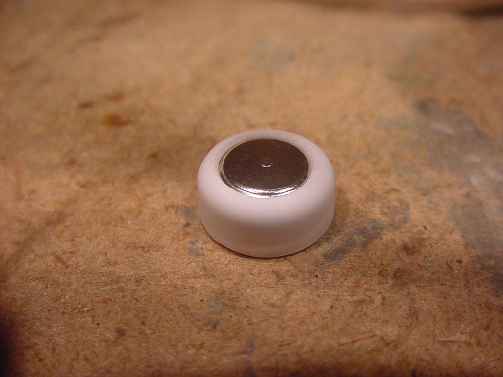
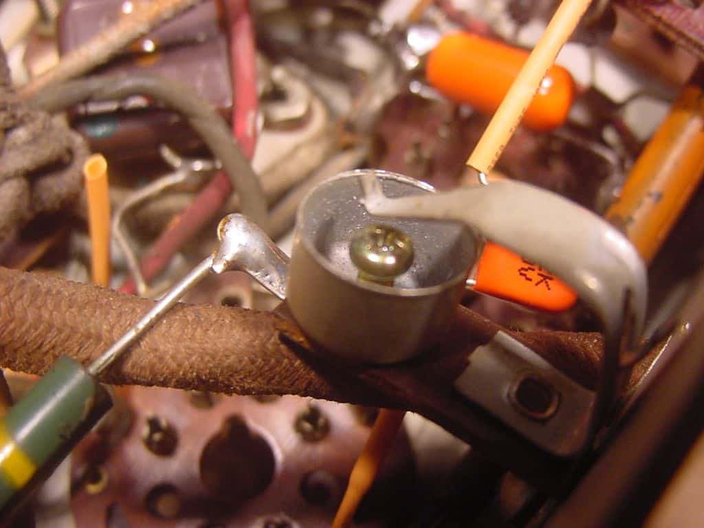
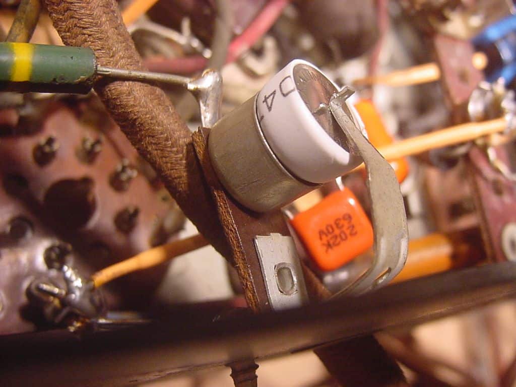
While restoring the electronics of a Marconi Model 142 that I recently acquired, I came across two ‘bias cells’ when I started to re-cap the chassis – I had heard of these gizmos and had even read about them, but had never actually seen them used before in a circuit (try the Philco Repair Bench and AWA Journal web sites for more info). The two bias cells in my Marconi were completely dead (they are supposed to read either 1.0volt or 1.25volt using a VTVM) and, although there are some methods of ‘rejuvenating’ them on the web (eg. placing in boiling water or drilling a hole and injecting water etc.), I decided to replace mine with modern-day alkaline cells. I used the readily-available type AG13-5 (the larger, fat ones that fit small laser pointers). I had to insulate the sides of the cell body using some heat-shrink sleeve (see photos) and adapt the sockets by inserting a central screw to allow installation of the cell the correct way around (without changing the holder’s wiring) as the modern cell has its +ve connection on the cell body (opposite to the bias cell construction). The new cell’s voltage is 1.5 volt, but they seem to work just fine in the Marconi: one is used to provide the delayed AGC bias to the 6A8 converter and 6K7 IF amplifier tubes, and the other to bias the grid of the 6F5 first audio tube. Why use ‘bias cells? – they became popular in the late 1930’s and, costing only 18c each apparently saved a couple of resistors and capacitors, thus saving a a total of some 24c cents in the production cost of the radio. The bias cell manufacturer, Mallory, claimed use of the cells had several technical advantages over resistor bias, including ‘noisless’ operation, simpler circuitry and that they provide a constant bias voltage regardless of the tube characteristics, thus reducing distortion. Seems like a backwards move to fit these in my books – apparently they had vanished from electronics parts catalogues by the early 1950’s. The manufacturers also claimed that they would last the life of the set as the current draw was effectively zero (I don’t supppose I could get my money back after 70 years could I…).
Gerry
Download DSC00041 [1024×768].JPG. (Caution: This file may not be virus scanned.)
Download DSC00037 [1024×768].JPG. (Caution: This file may not be virus scanned.)
Download DSC00178 [1024×768].JPG. (Caution: This file may not be virus scanned.)
Download DSC00050 [1024×768].JPG. (Caution: This file may not be virus scanned.)
November 2, 2008 at 5:35 am #1172Bill W-S
Forum ParticipantNice job Gerry! I just did one myself, a Rogers Majestic, but didn’t think of the shrink tube application and had to reverse the connections on the thing. Bill
November 5, 2008 at 4:24 am #1175Gerry O’HaraKeymasterWelcome to the site Bill! – could use a few of your excellent restoration examples here as posts.
January 21, 2009 at 4:16 pm #1262HolderAccount
Forum ParticipantGerry,
Great job. I’ve got a Rogers 13/70 waiting for a restore that also uses the bias cells. I’ll be attempting your method when I get to it. I’ve acquired all the tubes I needed which I think would have been the hardest part. Hopefully it’s all downhill from here.
Paul
February 6, 2009 at 5:43 pm #1291Gerry O’HaraKeymasterWell, would you believe it – I just found two bias cells lurking in a Rogers Majestic Model 870 (Chassis Type 8M-721). They had been replaced with alkaline cells at some point. Photos below.
Download DSC00037 [1024×768].JPG. (Caution: This file may not be virus scanned.)
Download DSC00031 [1024×768].JPG. (Caution: This file may not be virus scanned.)
September 3, 2025 at 8:48 am #34845 Gerry O’HaraCVRS Member
Looks like my original photos have gone ‘AWOL’ sometime over the last 16 years(!), so they are now attached to this reply.
September 29, 2025 at 10:05 pm #34863 Brad WinderCVRS Member
Looks good Gerry! I will use your method to replace cells next time I run across one.
-
AuthorPosts
![DSC00041 [1024×768].JPG](https://canadianvintageradio.com/wp-content/uploads/bbpress/1102/DSC00041 [1024x768].JPG)
![DSC00037 [1024×768].JPG](https://canadianvintageradio.com/wp-content/uploads/bbpress/1102/DSC00037 [1024x768].JPG)
![DSC00178 [1024×768].JPG](https://canadianvintageradio.com/wp-content/uploads/bbpress/1102/DSC00178 [1024x768].JPG)
![DSC00050 [1024×768].JPG](https://canadianvintageradio.com/wp-content/uploads/bbpress/1102/DSC00050 [1024x768].JPG)
![DSC00037 [1024×768].JPG](https://canadianvintageradio.com/wp-content/uploads/bbpress/1291/DSC00037 [1024x768].JPG)
![DSC00031 [1024×768].JPG](https://canadianvintageradio.com/wp-content/uploads/bbpress/1291/DSC00031 [1024x768].JPG)
- You must be logged in to reply to this topic.