Home › Forums › Electronics Restoration › Rogers Majestic 6M531
- This topic has 12 replies, 6 voices, and was last updated 3 years, 3 months ago by
Dan Walker.
-
AuthorPosts
-
May 15, 2016 at 4:40 am #7773
HolderAccount
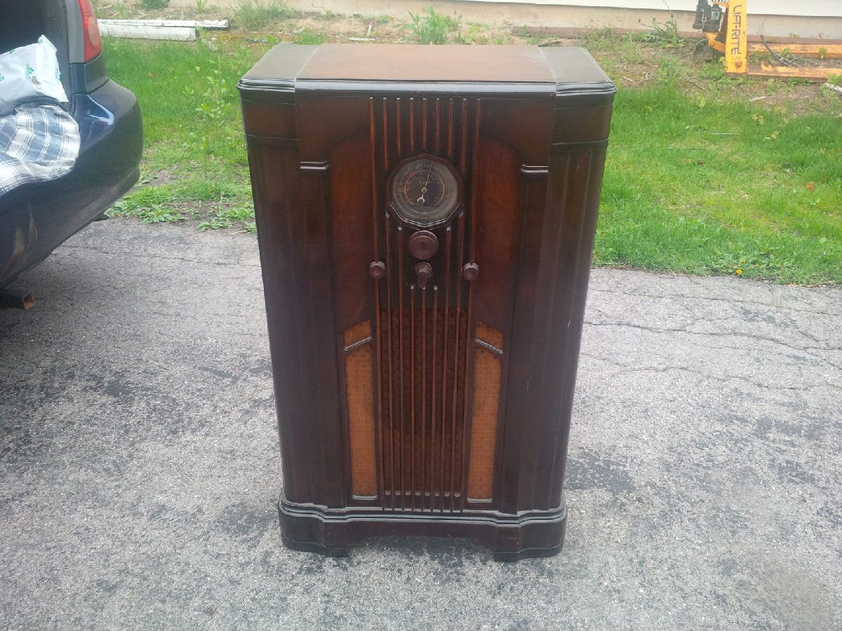
Forum ParticipantHello, everyone. I am very new to the hobby and just picked up what I think is a 1936 Majestic Cornwall, with a 6M531 chassis. Please correct me if I’m wrong. I have found a schematic for it. It looks as if, to my untrained eye and a quick examination, that it’s missing at least two tubes and needs a new power cord, and who knows what else (missing, broken, or otherwise in need of repair). So, in order to get this radio working, I would imagine that I’ll need to remove the chassis to replace the tubes and the power cord. While removed, I also assume that I should clean the whole chassis and the contact points for the working switches and what not. Is this also a good time to replace the capacitors as they will likely need replacing? I would like to be able to use this radio so I’d like to get it working well. I have not tested anything. Being new at working with these things, any advice would be appreciated. Thanks in advance.
May 15, 2016 at 11:46 am #7788Forum ParticipantAdvice on “how to proceed” with restoration is usually based on opinion, so here is mine :
– There is a difference between “repair” and “restore”.
– I like to “repair” first. That way I know if a set is worth “restoring”, or will it need something that I’d rather not pay for?
– I start by cutting out (electrically) the filter capacitors in the power supply, subbing in replacements with test leads, replace any obviously dangerous wiring, then give it a test run
– if it works when first plugged in to test … go ahead and restore, doing one part at a time followed by a test to make sure it’s done correctly
– if it doesn’t work when first plugged in to test … I do the repairs first, then proceed with the restorationAs I said …. that’s just my way … how you proceed is purely personal preference. You will want to choose the method that gets you where you want to go safely and most comfortably for you, with the least amount of electrical trouble.
Have fun.
May 16, 2016 at 8:05 pm #7789Forum ParticipantJamie,
Can you tell us the schematic source for the radio ? It may be RCC 18. That will
help in providing specific advice on how to proceed.Steve Dow
May 17, 2016 at 5:06 pm #7790Forum ParticipantThanks for your advice so far. I greatly appreciate it. I collect antique garden tractors mostly from the 1910s to the 1950s as my main hobby (I even have my own website dedicated to the hobby), and I’m finding that some ideas actually carry over between the two hobbies with just the details changing. That’s probably true of fixing and collecting many antiques. Presently, I’ll be “repairing” this radio to get it operational. I may or may not “restore” it, but definitely not any time soon.
As for the schematic source for the radio, I’m afraid you’ll have to tell me what that means as I’m not sure. I will get you the information as soon as I know what I’m looking for.
Again, thanks so much for your help!
May 17, 2016 at 9:55 pm #7792Dan Walker
CVRS Memberhttps://pacifictv.ca/schematics/rogers11-52data.pdf
This is a link that take you to Pacific TV and this is the schematic for your radio.
It is also listed as Rogers 11/52, 11/55, 11/56.
the schematic is a drawing of where the parts of the radio connect to each other.
This radio is a good one to start with as it is fairly simple in that it only has five tubes.
It is a good first project radio. you can get capacitors from ”just radios” and they are located in Ontario.
I hope this helps. We have a lot of good people here that can help you out with repairing the radio.
I started out knowing nothing about how a radio works, and if I can do it anyone can
Dan walker in CalgaryMay 18, 2016 at 4:38 am #7793Forum ParticipantOh, I’m sorry. Now I know exactly what you mean, Steve. I have no idea why, but I thought Steve meant something else. My mistake; I somehow managed to misunderstand. As soon as I arrived home with the radio I was able to find that schematic and took a quick look at it to see what obvious things I was missing. Thanks, Dan. And when it says tubes “C-40″ and C-41”, are those specific tube part numbers, or just the way Rogers (or the person who created the schematic) chose to label them? In other words, are there C-40 and C-41 tubes, or are they in fact called something else? I’m sorry for the very basic questions, but I promise that, as a general rule, I do learn somewhat quickly.
May 18, 2016 at 8:15 am #7794CVRS MemberJamie;; C40 and C41 are not tubes , they are the electrolytic capacitors that must be changed, your tubes are 6A7, 6K7, 75, 6F6, and the rectifier tube which is an 80.
If you look at the parts list you will see that C40 is 25 mf and C41 is 16 mf. As you are looking at the schematic
the top part of C40 and C 41 are the positive ends of the capacitors [caps]. The voltage for these cap is not stated, so personally I would use 600 volt caps. It is VERY important that these are installed with the proper polarity. I am not sure about your specific radio but these two caps might be in one metal can sitting on the top of the radio chassis. If it is then you can just leave it there and put the new caps under the chassis, disconnecting the old cap
These capacitors smooth out the dc voltage so it does not have any ripples in it.
I sure this sound technical to you be it is not THAT hard, once you do it once ..
In order to understand all this I suggest you read the book ”elements of radio” by Marcus and Marcus.
It can be downloaded from the antique radio forum [ARF].
It explains how a radio works in simple layman’s terms.
I hope this helps you get things going
Dan Walker in Calgary-
This reply was modified 3 years, 4 months ago by
Dan Walker.
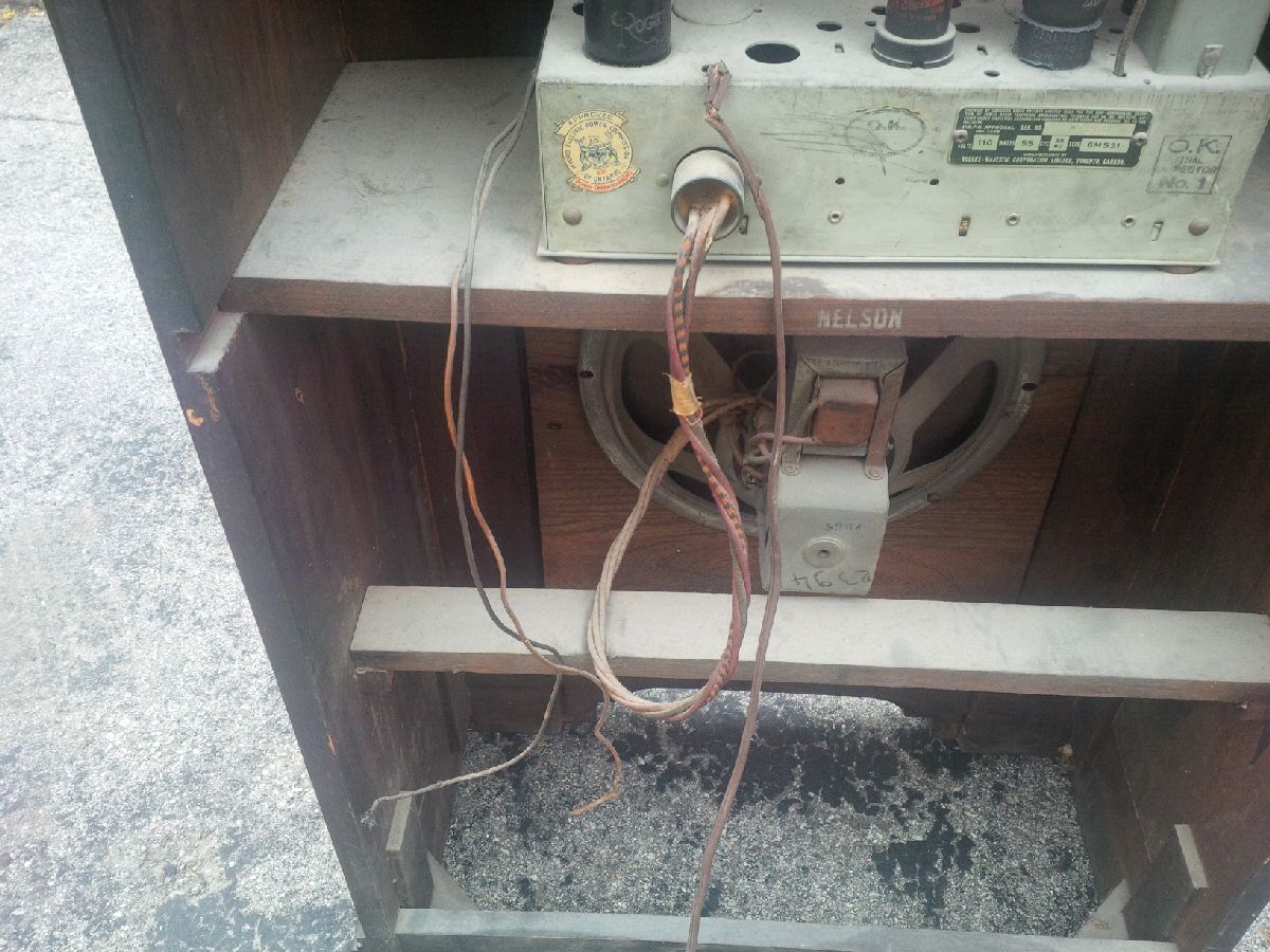
May 18, 2016 at 5:07 pm #7797Forum ParticipantIf you take a look at IMG908 on the LHS of the chassis you will see that there are two holes. Those holes are where capacitors # C40 and C41 used to sit. Looking at the chassis layout in the linked schematic confirms this. Also looking at the schematic shows that ONLY C41 has a negative side connected to the chassis Watch for this when you replace them. While this is not “uncommon”, it is more common for the negative sides of filter capacitors to be connected together and also to the negative side of the high voltage circuit (B-).
May 20, 2016 at 8:55 am #7798Forum ParticipantThank you, Dan and John. I am hoping to remove the chassis this weekend. I’ll be taking my time on this and am in no hurry. I will definitely be utilizing the information and advice that you guys here are giving to me. It’s extremely helpful. I also have a couple of books on tube radio repair but have yet to peruse them. I will be reading them as well. I’m sure I’ll have many questions throughout this process. Thanks again!
June 6, 2016 at 3:22 pm #7840Forum ParticipantSo I went to remove the chassis from the cabinet but wanted to ask two questions first, BEFORE I do anything ill-advised causing damage that could have easily been avoided. First, do the wooden control knobs just pull off or is there a trick to them? I don’t want to break them or anything else when removing them. I assume they just pull off, but assumptions can sometimes be dangerous. Secondly, is there anything special attaching the dial to the cabinet or should it just pull away as I pull the chassis away? I don’t seen anything, but I didn’t want to bend or break any pieces of the dial when pulling the chassis away. I know that this is painfully basic stuff, but it’s better to be safe than sorry, very sorry. I’m sure that I’ll make some ignorantly poor choices at various points throughout this process (live and learn), but I’d like to minimize those moments as much as possible.
June 6, 2016 at 4:36 pm #7841Greg Bilodeau
Forum ParticipantJamie, there are most likely some little set screws holding those knobs in place. Look for a little hole in the sides of the knobs and there will be a little straight blade set screw in there. If no holes then they just pull off.
There should not be anything holding the dial but with that said go slow and be careful making sure nothing hangs up or seems stuck. It should slide out nice and easy once the chassis bolts are removed.Gregb
February 22, 2023 at 8:14 am #18153Rhys Rissman
Forum ParticipantI also have one of these radios. The site I use often for schematics is the radio museum. https://www.radiomuseum.org/act_main.cfm This link may help.
https://www.radiomuseum.org/r/rogerstube_majestic_cornwall_ch_6m53.htmlFebruary 26, 2023 at 8:20 am #24209CVRS MemberI have the table version of this radio.
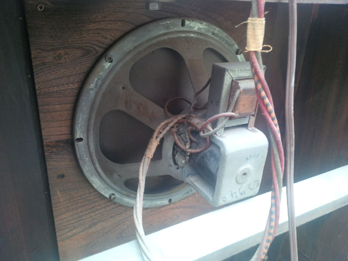
. I can’t tell by the photos ,but there should be a tube [looking from the rear] at the front right .
Those two holes you see are where there used to be two electrolytic capacitors. [C40 and C41]
They were probably replaced sometime in the past with newer ones mounted under the chassis.
http://pacifictv.ca/schematics/rogers11-52data.pdf
This is a link to Pacific TV for the schematics. it also shows you where the specific tubes go.
You will notice that on the schematic there are two bias cells. BC 1 and BC 2 These can be replace with two 1.5 volt watch batteries.
You will need to spray the volume control with a lubricant as they seem to gum up after age.
If your radio does not have a 75 tube You can use a 6Q7 tube.
Feel free to send me an email if you have any questions about the bias cells.
I am no expert on radio repair but I have worked on several Rogers radios, and this one is pretty basic.
The cabinet should not take much to get it presentable.
good luck
Dan in Calgary -
This reply was modified 3 years, 4 months ago by
-
AuthorPosts


- You must be logged in to reply to this topic.