Home › Forums › Electronics Restoration › Westinghouse model 780-B
- This topic has 13 replies, 3 voices, and was last updated 2 months, 1 week ago by
 Rick D.
-
AuthorPosts
-
October 8, 2025 at 3:26 pm #34871
 Rick DCVRS Member
Hello , I want to restore a Westinghouse model 780-B ,any chance anyone has a good schematic and a parts list , would be very thankful if you could share it with me , thanks for your time all the very best Rick
October 8, 2025 at 4:10 pm #34872Jim Sirtonski
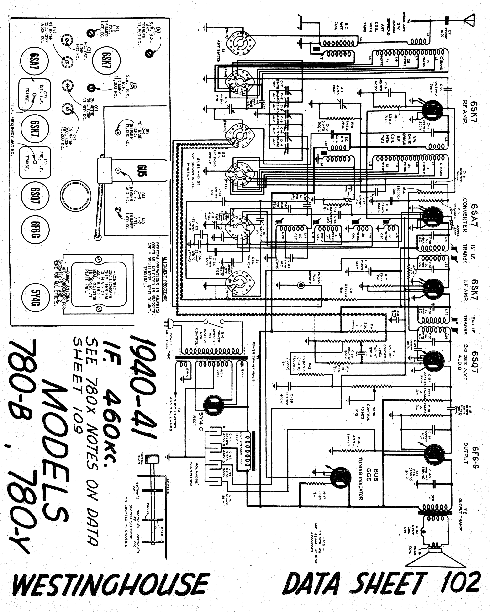
CVRS MemberHere’s a schematic Rick. First glance looks a bit grainy but if you zoom in it’s quite clear. I’ll try to find a parts list as well but I don’t think there was one published in the RCC manual.
Jim
October 8, 2025 at 4:13 pm #34873CVRS MemberFile was too large. Hope you can read a png file.
Jim
Attachments:
October 9, 2025 at 11:21 am #34875Rick DCVRS MemberThanks Jim your right if I zoom in it is quite clear , thanks so much , I would love to have the parts list if you find it, thanks again all the very best Rick
October 10, 2025 at 6:44 pm #34876Rick DCVRS MemberHello again , can anyone tell me how to count the tube base PIN numbers ,on most schematics you se the tube key slot and count from there counting clockwise or they are numbered on the schematic, I don’t see the key slot on the schematic , some one along the way has messed with this set and I want to check all connections and follow them to make sure they are correct, I know this takes a lot of time but I want to be sure everything is as it should be and I need to know the tube PIN numbers so I can trace all wires and parts , thanks for any help all the best Rick
October 10, 2025 at 7:43 pm #34877Dan Walker
CVRS MemberHi Rick.. If you have a book showing the tubes [like an RCA tube book] , you can look up the tube and
it will point out the grid , heaters etc, and it will tell you the pins numbers on the tube then you can look at the schematic and
go from there. I hope This is not too confusing.
Dan in CalgaryOctober 11, 2025 at 4:17 am #34878Rick DCVRS MemberHello Dan , I have a tube book and I see the PIN numbers for the plate heater ect but if you look at the schematic I have here posted above and it is a clear one if you zoom in I don’t see on the schematic the PIN numbers or even the locking key or even what shows the plate or heater or anything I can find on the schematic , I can find the PIN numbers on the chassis tube base but how do I check that with the schematic that has no numbers or a marking that indicates heater plate or anything that I recognize, is the schematic pins for plate heater etc marked in a special way that I don’t understand , any help to read the PIN numbers on the schematic would be appreciated, thanks for your time all the very best Rick
October 11, 2025 at 7:48 am #34879CVRS MemberHello Rick. I know what you mean,when I see the schematic..
How do they expect someone to read it like that???
I had a table model 780, but I sold it.
The RCC book is supposed to have the schematics on page 102 and 109. I will have a look at my books
and see if I can come up with a better schematic.
Dan in Calgary.October 11, 2025 at 9:28 am #34880CVRS MemberHello Rick,
I downloaded this from RadioMuseum several months ago. It was published by Curt Bowles and it will give you a much better look at the pin designations. The only variance I found from the original is what he identified as C18 and gave it a value and composition of 8.2pF mica. The original schematic shows this as a loose coupled 2pF and that is what I installed in the 780-Y that I worked on. Good luck.
JimAttachments:
October 11, 2025 at 11:53 am #34882Rick DCVRS MemberHi Jim thanks so much that’s what I needed now I can trace and check all parts and follow the wires
and make sure it’s the way it should be from tube to tube thanks ever so much fellows for the help
all the very best have a great Thanksgiving take care RickOctober 11, 2025 at 3:57 pm #34883CVRS MemberHi Rick it looks like you found what you needed.that is a much better schematic.
I phoned you but disregard it
Dan in CalgaryOctober 14, 2025 at 6:32 pm #34887Rick DCVRS MemberHello fellows , the set is working just fine now , I found that condenser #42 @ 15 uf was wired to where the condenser #43 @ 5 uf should be and the condenser #43 was wired to where the #42 should be , and one condenser #40 @ .005 was missing not there and one resistor #14 @220K tested at 7.5 Meg on all three of my testers so I replaced that , it’s frustrating when you get a set that some one has messed with but with the schematic that Jim sent me it made bringing it back to where it should be a lot easier,thanks again Jim and Dan for the help , all the very best Rick
October 14, 2025 at 6:38 pm #34888Rick DCVRS MemberOne thing I meant to say that resistor # 14 @ 220 k was tested out of circuit when it tested at 7.5 Meg ? , never seen one drift that far
November 9, 2025 at 10:11 am #34959Rick DCVRS MemberHello fellows I now have finished the Westinghouse 780-B all caps except the mica or the ones that look like a domino with the dots all the others were changed for new ones and all resistors changed , some were fine but it’s time I started using some of my stock , set works fine back in the cabinet now one thing I have noticed is every now and then when I turn on the set I hear a snap noise after that the set comes on and plays great , what would cause this and is it a problem and could there be some thing wrong with the set and this might cause some damage in the future , anyone had this problem I know I have heard this snap at times on other old sets but only when I turned the set off , just thought I would ask to be sure it’s ok , all the best Rick
-
AuthorPosts

- You must be logged in to reply to this topic.