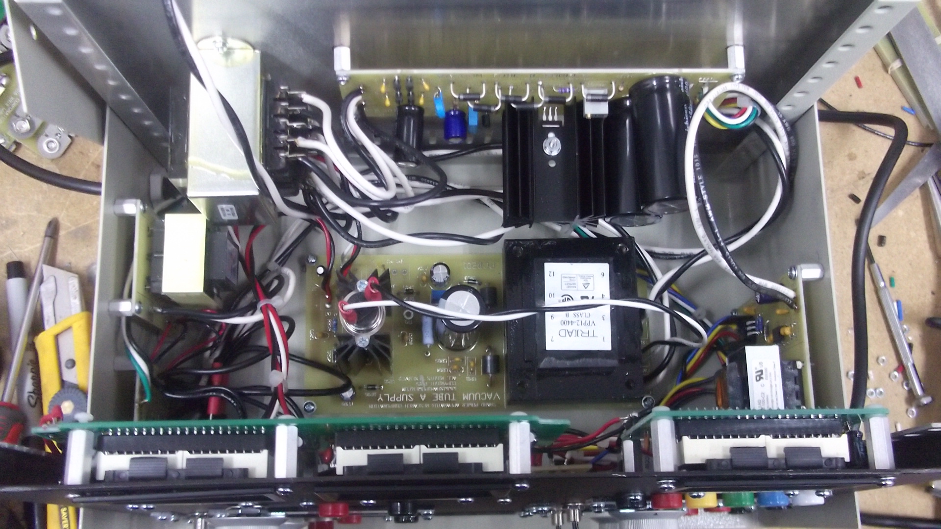
For testing and troubleshooting DC operated radios. I took the modular circuit boards from my Smart Power Supply and came up with the following. Looking to start that build next month. Specs:
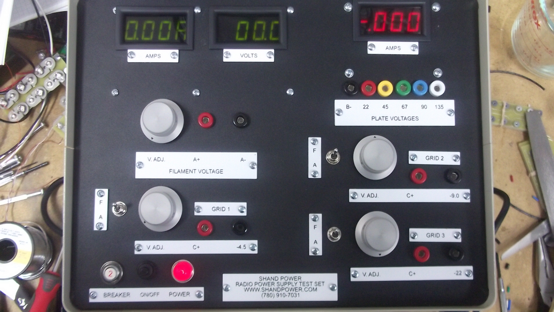
1. Power input: 120 VAC, 60 Hz. Circuit breaker protected. On-Off switch with power indicator on the front panel.
2. Filament: 0 – 6.3 VDC, 2.5 A. Voltage and current meter provided.
3. Plante: 22, 45, 67, 90 and 135 VDC, 60 mA maximum. Current meter provided.
4. Grids: 3 independent voltages: -4.5, -9 and -22 VDC, 20 mA each. Voltages can be fixed or adjustable.
5. All adjustments use multiple turn potentiometers.
6. Fan cooling.
7. Dimensions: 12″ W x 9″ H x 8 “D
8. Weight: 10 lbs.
 .
.