Home › Forums › Electronics Restoration › Philco Model 90 mod
- This topic has 4 replies, 3 voices, and was last updated 6 years, 1 month ago by
 John Greenland.
-
AuthorPosts
-
February 22, 2016 at 11:04 pm #7424
Rick Rova
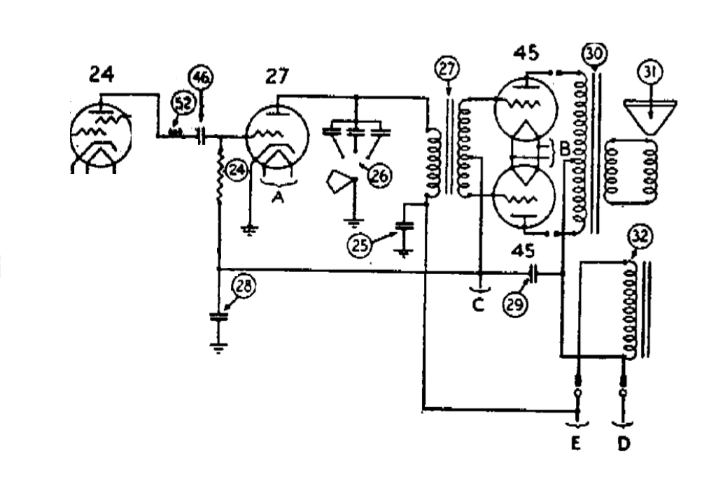
Forum ParticipantThe Philco Model 90 I’m try to repair was worked on previously and the circuit was modified from the original. The final audio transformer just prior to the Type 45 tube push-pull section was removed and replaced with a different circuit. Not being electronically savvy enough to determine if this is a problem I have attempted to trace through the rats nest of wiring and components and created the attached schematic of this section. I’ve attached the same section from the original schematic for comparison. If anyone on the forum could let me know if this modification is OK, or if I should attempt to restore the original configuration I would be grateful! (Note, the tone section was also totally disconnected.)
February 23, 2016 at 2:12 pm #7434Forum ParticipantHere’s the rat’s nest view…(some might call this obsessive 😉 but it helps me to trace through the wiring and verify the layout. (The little squares with the light gray lines connecting them are my way of showing terminal strips)
Attachments:
February 25, 2016 at 12:16 am #7441Forum ParticipantAn update to the wiring diagram, I’ve noted a half dozen wiring errors, 1 incorrect valued resistor, and 3 missing components (2 resistors and a cap). I also verified 2 suspect coils by taking them out of the circuit and measuring them (all good, whew! no rewinds) and then rewired with new vintage-style cloth wire. I also repaired a loose ground wire. Getting closer to plugging it back in for more tests!
Attachments:
November 12, 2019 at 8:12 pm #12224Darren
CVRS MemberI also have a Philco 90 with push pull 45’s, and like you someone modified this set, AND also like you I’m not tech savy enough to figure out what this person did, all i know is that he bypassed the first audio transformer as the primary in it was toast, the radio plays but has very weak volume. as the only power to the speaker is coming off the plate of the last 27 tube and going to the output transformer on the speaker. There are a number of caps and resistors missing, my head is spinning from trying to figure this mess out! so my question to you Rick you show a drawing of the wiring that has all the resistor and cap values, how does this set perform the way your drawing depicts this wiring? I know this is an old thread, just wondering how you made out with it?
thanks
November 14, 2019 at 3:45 pm #12228 John GreenlandCVRS Member
Hi Rick,
A couple of things about the mod sort of jump out at me.
1: There is no plate resistor on the 27 tube. The signal from the plate of that tube goes basically to ground. The mod was an attempt to create a phase splitter circuit from existing hardware so that the 2 output 45’s would have opposite signals on their control grids. Without a resistor in the plate circuit there will not a signal for one of the 45’s.
2: There is no negative bias applied to the grids of the 45’s. This would have come from point “C” in the original circuit and is a result of the resistor in the ground/common connection of the power transformer being routed thru a resistor. The voltage is probably around 40 volts or so. There also does not appear to be any bias for the 27 tube as well.
Hope this helps.
John G. VO1 CAT
-
AuthorPosts
- You must be logged in to reply to this topic.