Home › Forums › Electronics Restoration › Need help with troubleshooting vintage Philco 1708 radio/record player
Tagged: 1708, Philco, Phonograph, Radio, vintage
- This topic has 11 replies, 4 voices, and was last updated 4 weeks ago by
Andrew Black.
-
AuthorPosts
-
April 4, 2025 at 7:12 pm #34448
Biker
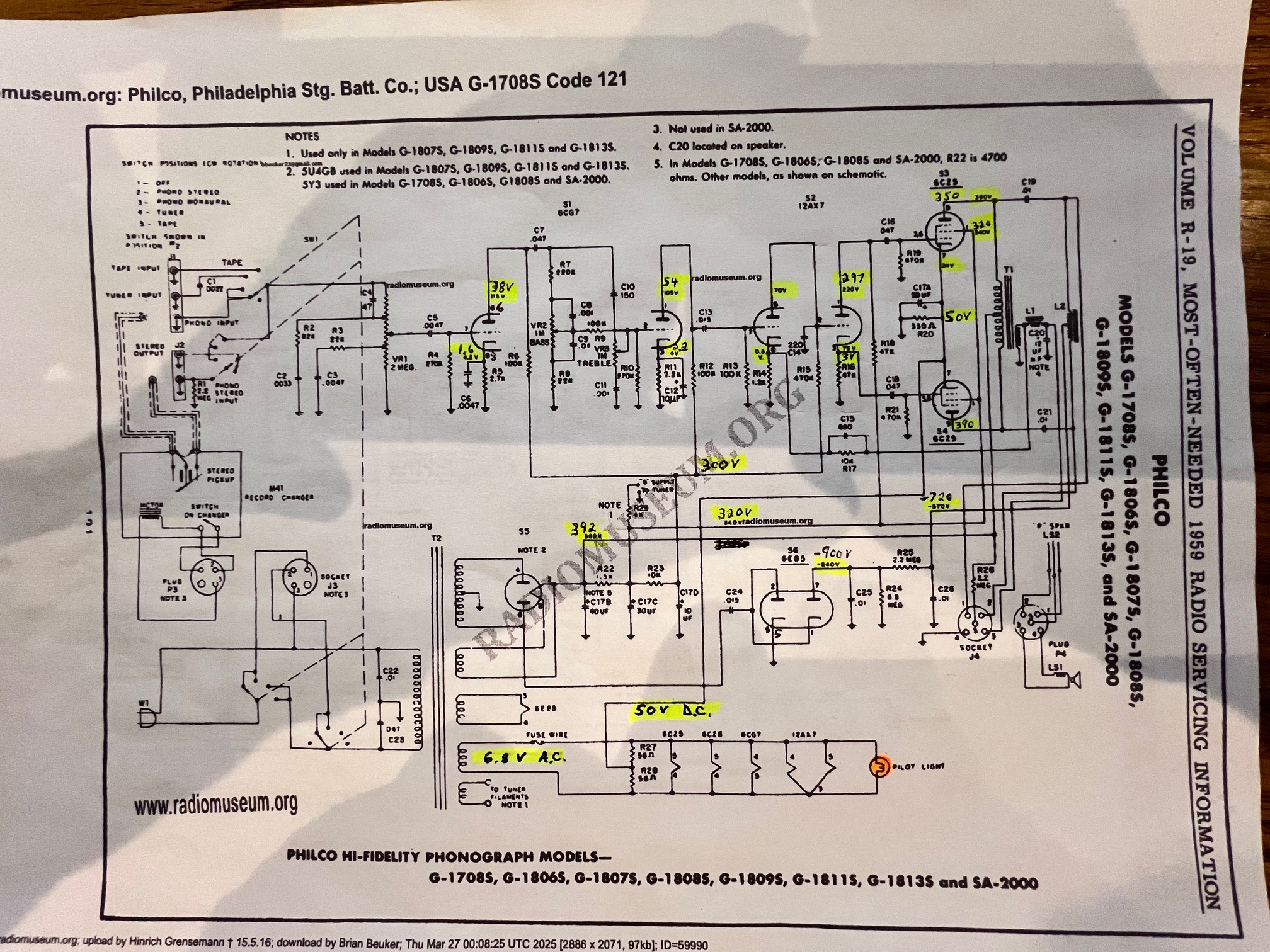
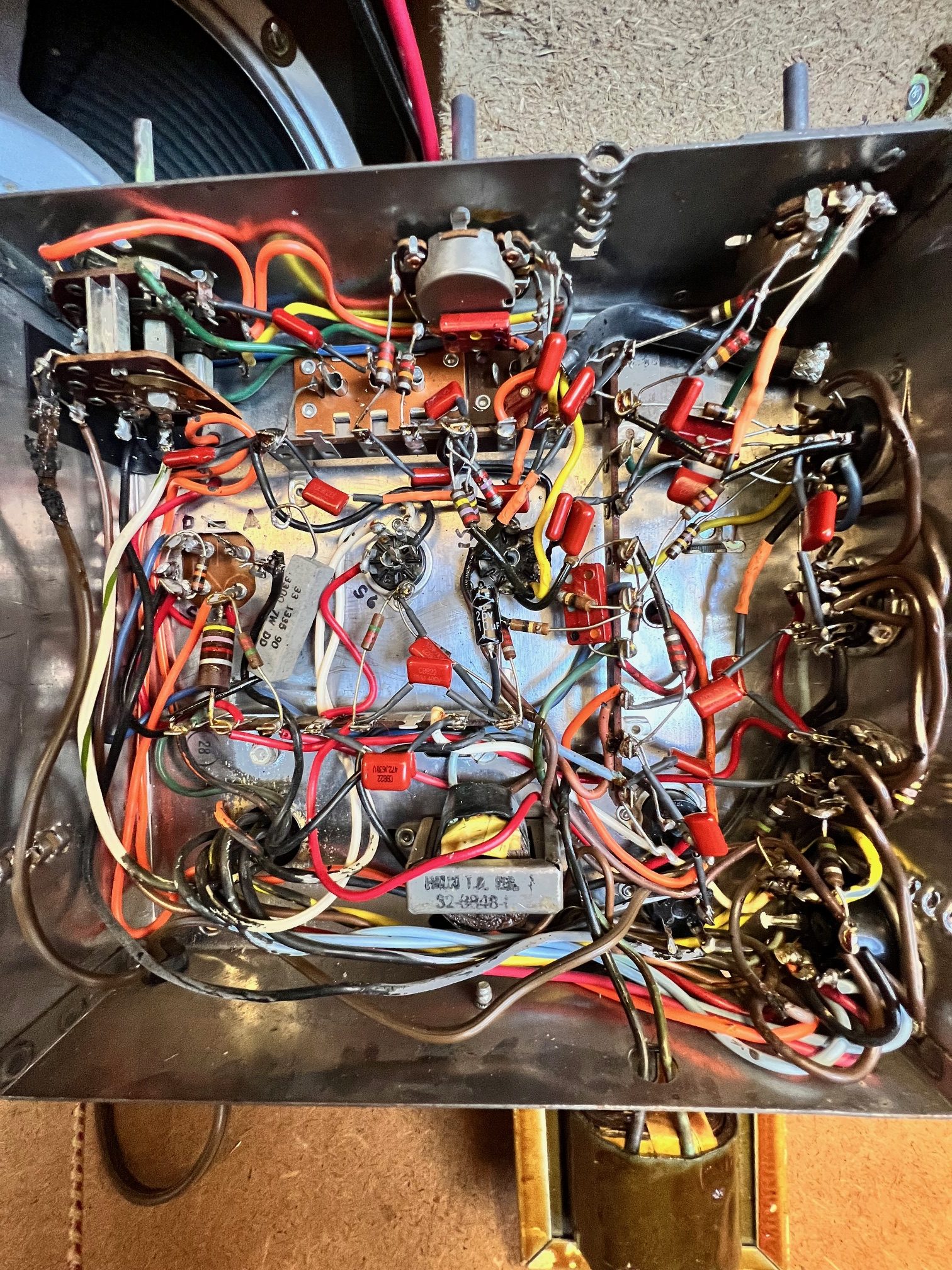
Forum ParticipantI’m a newbie to troubleshooting and repairing vacuum tube electronics, so am needing some help. I’m hoping to get this 1959 Philco 1708 console record player working. The amp currently is not working on it. I started by replacing all the caps in the amplifier that were paper or electrolytic caps. There is one 4-in-one can capacitor however that I haven’t replaced yet as I haven’t sourced it yet. I’ve tested all the tubes with a tube tester and had to replace one of the 6CZ5 tubes. I noticed the two 6CZ5 tubes are red plating, so I’ve limited my troubleshooting to brief “on” periods. I’ve attached a schematic with voltages that I’ve measured(written in pen) as compared to what they should be(typed). It appears as though pins 7 on the 6CZ5 tube, what I think is the grid bias, is about double what it should be. I’m not sure how I go forward from here to try and fix that, as I don’t know the vacuum tubes at all. I’ve attached a link to schematics and parts lists if needed. Would appreciate any help you can provide. Thanks.
April 5, 2025 at 7:25 am #34454Dan Walker
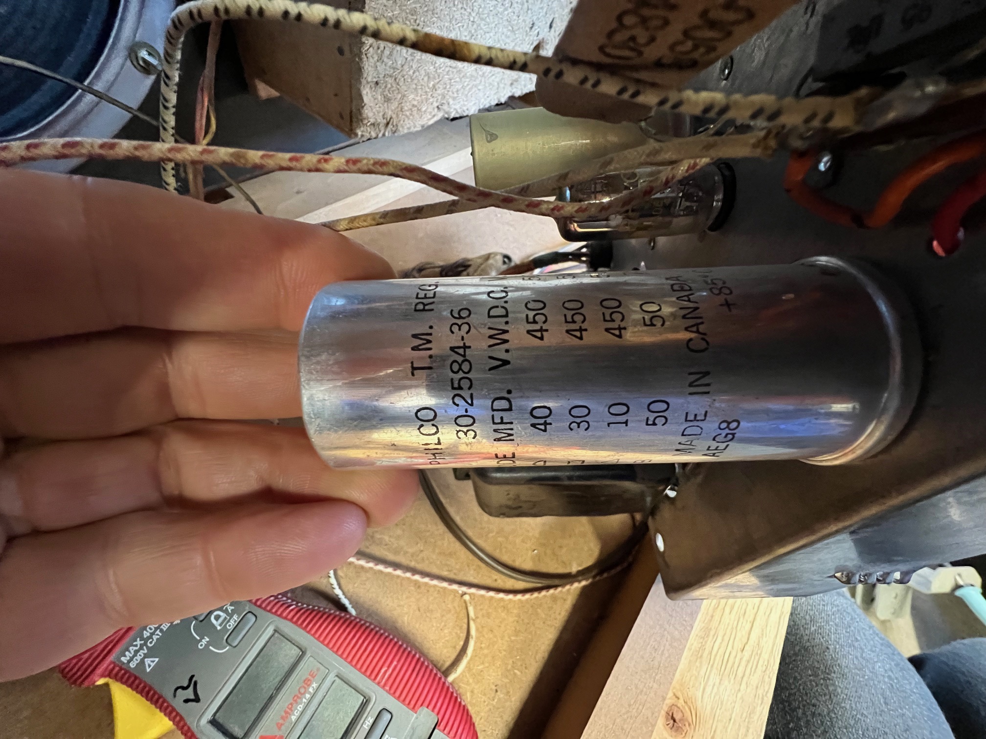
CVRS MemberThe caps you DID NOT change are about the most important.
They are the electrolytic caps and are part of the power supply.
They are C17b=40
C17C=30
C17B=10
C17A=50.
On the can it tells you the voltages for each cap.
What most people do is use individual caps under the chassis and replace these one at a time,
using the same values. The voltages on the new caps can be larger BUT the micro farad values must be at lease the same as the original valuesIf you look at the can you can see a triangle,a square and a half moon and one with no sign.
NOW—– looking under the chassis at the bottom of the can ;the can has those symbols.
sometimes they are sort of hard to see BUT they are there,,,, indicating where that specific positive lead comes from the can.
Most likely the can itself is grounded to the chassis by one of the lugs.The negative from these caps all go to chassis ground.
You might see if there is someone in your area who could help you outI hope my information helps you
Dan in CalgaryApril 6, 2025 at 9:32 am #34462Forum ParticipantThanks Dan. That’s exactly where I was thinking I needed to go next. I had already figured out the pinouts of the can and labeled it inside the chassis. Sourcing the can is difficult, so replacing them individually is a great idea. Any suggestions on where to source them, as I don’t think most of these are standard values?
I am quite familiar with electronics circuits and troubleshooting, just not vacuum tube electronics which is a new learning curve for me.
Thanks so far for your help.April 6, 2025 at 9:43 am #34463Forum ParticipantIf I can’t easily source the polarized caps in the value I need, I was thinking of connecting multiple caps in parallel to make the right value, such as a 47uF, 450v in parallel with a 3.3uF 450v to make up my 50uF one. Would you recommend not doing that for any reason?
April 6, 2025 at 1:32 pm #34464CVRS MemberI get all my capacitors from Just Radios https://www.justradios.com/cart.html
He takes pay pal
A lot of guys buy from him.. although he is in Canada,,,,he charges you in American dollars.
There is not much we can do about it but he carries a good selection and shipping is fast.
I would buy them from him and install them under the chassis.It is a real pain to make up your own in parallel.—— This way there is only one cap for each value.
The new caps area lot smaller than the old ones and there is usually room,
but you might have to use some terminal strips.
Good luck
Dan in CalgaryApril 6, 2025 at 2:57 pm #34465 John GreenlandCVRS Member
Hi all, greetings from the eastern edge of the continent.
While it might seem to be a good idea to parallel caps to get a particular value,
you must keep in mind that most of these electrolytic caps have tolerences of 20 % or more.So unless you absolutely need a specific value, over the counter values will suffice.
TTFN
April 6, 2025 at 4:19 pm #34467Forum ParticipantSo John, what you are saying, if I’m understanding you correctly, is that for a 50uF replacement, just use a 47uF cap, and for a 30uF, just use a 33uF?
April 6, 2025 at 5:22 pm #34468John GreenlandCVRS MemberYes.
When I do replacements, I personally try to get within 10 or 15 %. ( 20 % only if nothing else is available or for an initial test )So if you require a 45 and have a 50 , I would use it.
I would not use a 60 because it is 1s higher than the 45 by about 33 %.And then there is the possibility the replacement’s value is 20 % or more, higher than it is labelled.
I use the same rational with solid state.
Again , I say, this is personal choice.
TTFN
April 6, 2025 at 5:24 pm #34469John GreenlandCVRS MemberSorry about the couple of spelling errors. A trip to Staples might be in order for a new keyboard !
July 9, 2025 at 10:31 am #34748Forum ParticipantSorry guys, I kinda took a break from troubleshooting this, as along with spring and summer came a lot of other work as well that I needed to get caught up in. I have worked on this project some as well along the way. I’ve got all the caps replaced(except for the mica caps) and have checked most of the resistors and replaced some of them that were out of tolerance. After all that, I still don’t have a working system. I’ve noticed that the chassis is floating at 106vAC, so I’m wondering if this is supposed to be, or is this a problem I need to fix next? Looking forward to your guidance. Thanks!
July 9, 2025 at 11:47 am #34749Forum ParticipantI may have gotten this part fixed. I noticed when I replaced the four-in-one can caps with new ones, I tied them all to the ground, but then didn’t keep the chassis tied to ground at that point. After connecting the chassis to ground(the green transformer wire), I then had the chassis still floating at 18v, but my system now works. Yay! Question now is, is a floating 18v chassis normal for this vintage system? This only has the original two wire power cord. Can you convert to a three wire cord and tie chassis and all grounds to actual ground, not just to neutral as it is now?
On another note, I would like to find a new stylus for this system and wondering if anyone can suggest a source for that?Thanks,
BrianOctober 21, 2025 at 5:55 pm #34916Andrew Black
CVRS MemberHello Brian,
A local fellow has quite a selection of old styli. If you are still looking, let me know what type it is.
Andrew
-
AuthorPosts
- You must be logged in to reply to this topic.